
 EN
EN
 ar
ar bg
bg hr
hr cs
cs da
da nl
nl fi
fi fr
fr de
de el
el hi
hi it
it ko
ko no
no pl
pl pt
pt ro
ro ru
ru es
es sv
sv tl
tl iw
iw id
id lv
lv lt
lt sr
sr sk
sk sl
sl uk
uk vi
vi et
et hu
hu th
th tr
tr fa
fa ms
ms hy
hy ka
ka ur
ur bn
bn mn
mn ta
ta kk
kk uz
uz ku
ku
Real-Time Dam Safety Alerts with Differential Pressure Water Level Sensors
Key Takeaways An alert chain needs more than a sensor: define field in...

Wheatstone Bridge Strain Gauge: Principles and Practical Selection
Most engineers encounter the Wheatstone bridge circuit long before they ever handle a real strain gauge. It’s one of those rare concepts that sounds intimidating in a textbook but turns out to be quite practical on a test bench. At its core, a Wheatstone bridge strain gauge setup is about converting tiny resistance changes into readable voltage signals. Instead of treating this as pure theory, Kingmach focuses on the aspects that matter during field deployment: consistent gauge factor values, stable lead‑wire compensation, and packages that don’t fight you during bonding. Whether you’re instrumenting a bridge bearing or tracking stress on a turbine shaft, the electrical details tend to get overlooked until something drifts unexpectedly. This page collects the technical parameters that help you match a gauge to your logger and your environment without guesswork.
Technical Detail
A Wheatstone bridge strain gauge works on a simple premise: a resistive foil pattern deforms with the test surface, and that deformation alters the resistance. The bridge converts this change into a measurable voltage. What gets complicated is making sure the numbers stay reliable across temperature swings, long cable runs, and less‑than‑ideal surface finishes. Kingmach supplies gauges with standard resistances—commonly 120 Ω, 350 Ω, and sometimes 1000 Ω for low‑power or long‑range applications. The gauge factor typically sits around 2.0 for constantan foil, and the grid patterns range from single‑axis linear designs to stacked rosettes for biaxial stress analysis. One parameter that does not show up on datasheets but matters in practice is lead‑wire desensitization. When you add extension cables to a quarter‑bridge setup, the extra resistance acts like a voltage divider and can drop the apparent strain reading by a few percent. Three‑wire quarter‑bridge connections compensate for most of this, and all Kingmach gauges support that wiring right out of the package. For installations that need full‑bridge configuration, the built‑in temperature compensation curve is matched to common structural materials—steel, aluminum, and concrete. The self‑temperature compensation (STC) number on the gauge packaging tells you which material it’s intended for; using an STC‑13 gauge on aluminum will give you more thermal output than you probably want. Compatibility with data acquisition systems is mostly about excitation voltage and signal‑to‑noise ratio. Most loggers supply 2.5 V or 5 V excitation. At 350 Ω, a 5 V supply puts about 14 mW into the bridge, which is fine for static readings but can cause self‑heating drift on thin polymers. Kingmach’s specification sheets list the recommended excitation range for each grid size and backing material, so you can avoid that trap. For projects where off‑the‑shelf gauges don’t fit, we routinely adjust grid length, backing thickness, and solder pad layout—small changes that make installation faster without altering the bridge behavior. Since the company operates a global distribution network, technical questions about gauge compatibility with specific loggers (Campbell Scientific, HBM, National Instruments, etc.) get answered from field experience rather than generic manuals.
News
Key Takeaways An alert chain needs more than a sensor: define field in...
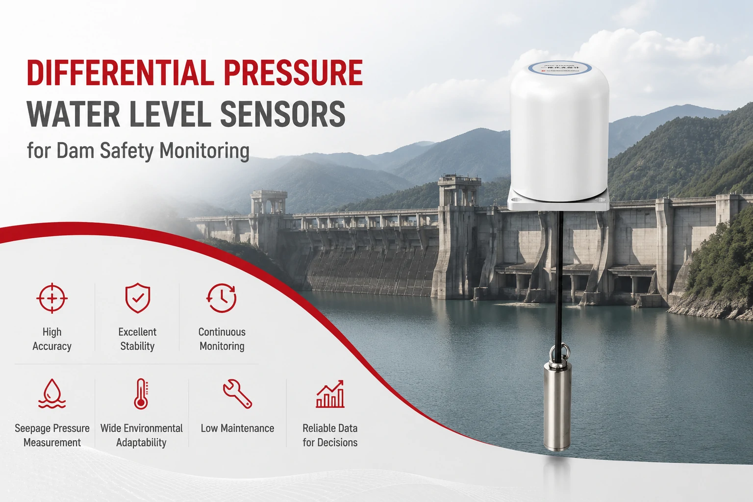
Key Takeaways The strongest fit is usually a confined, submerged, or s...
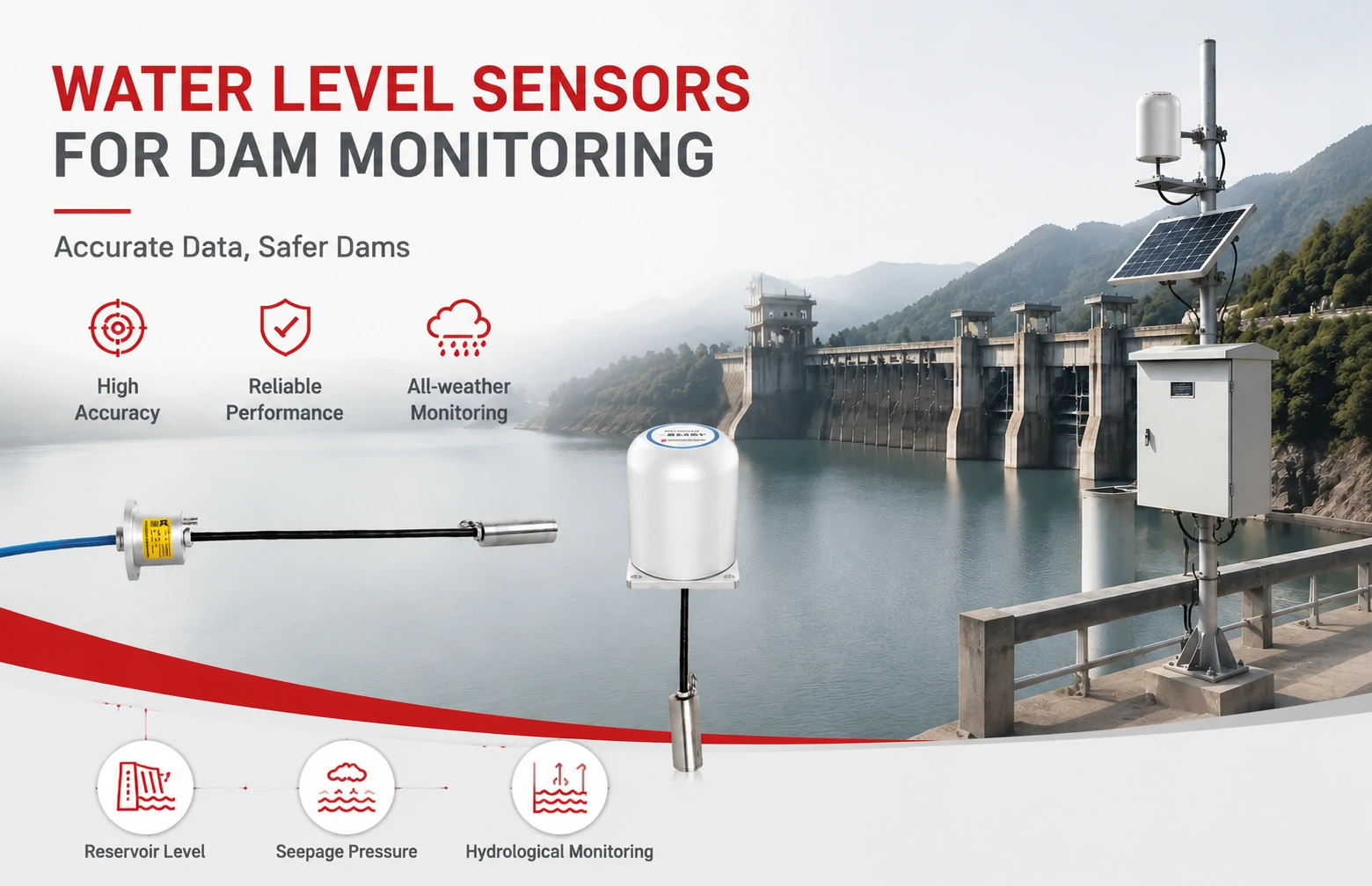
Kingmach Water Level Sensors for Dam Monitoring: A Buyer's Guide to Differential Pre...
Products
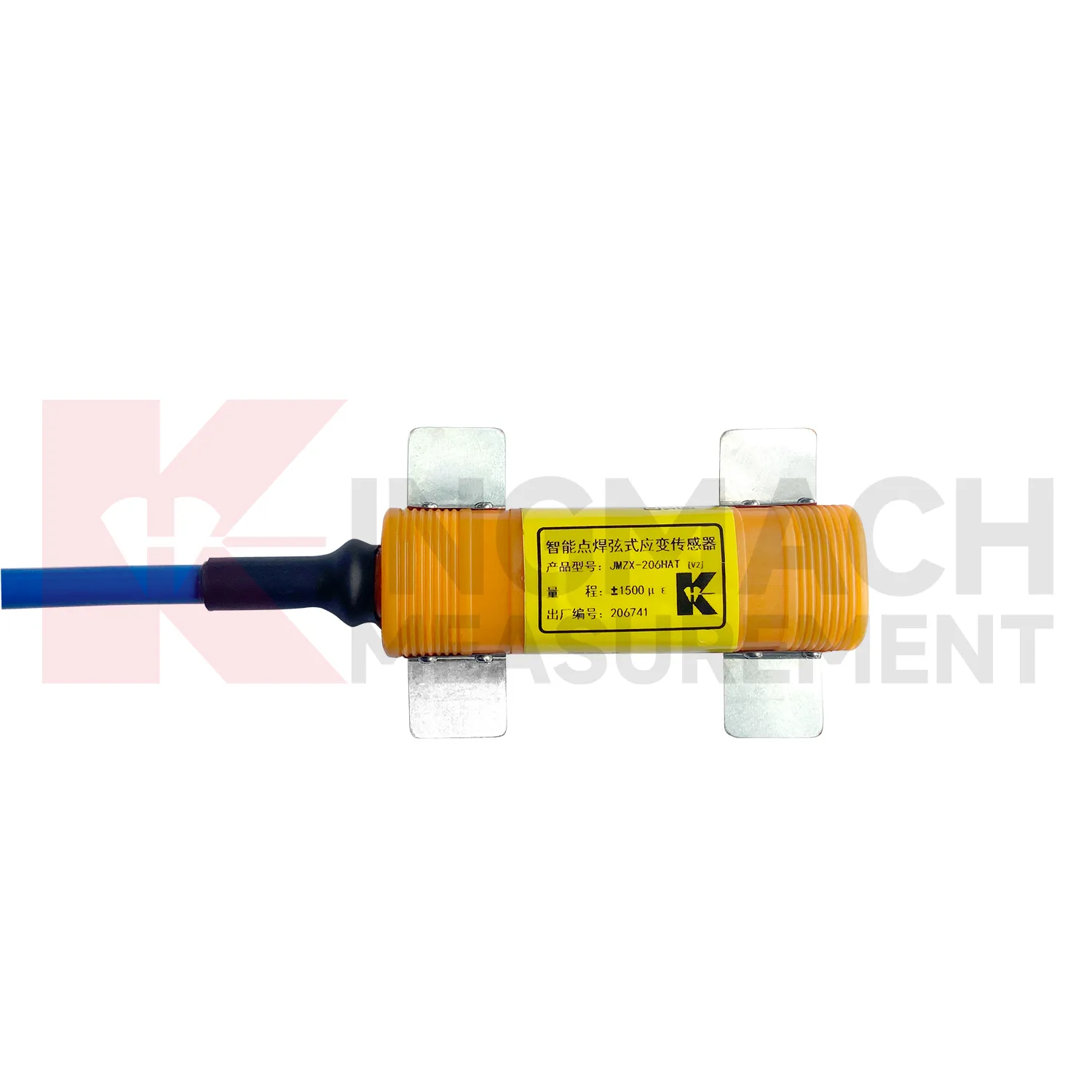
Smart vibrating wire strain gauge (surface welded model) JMZX-206HAT
View Details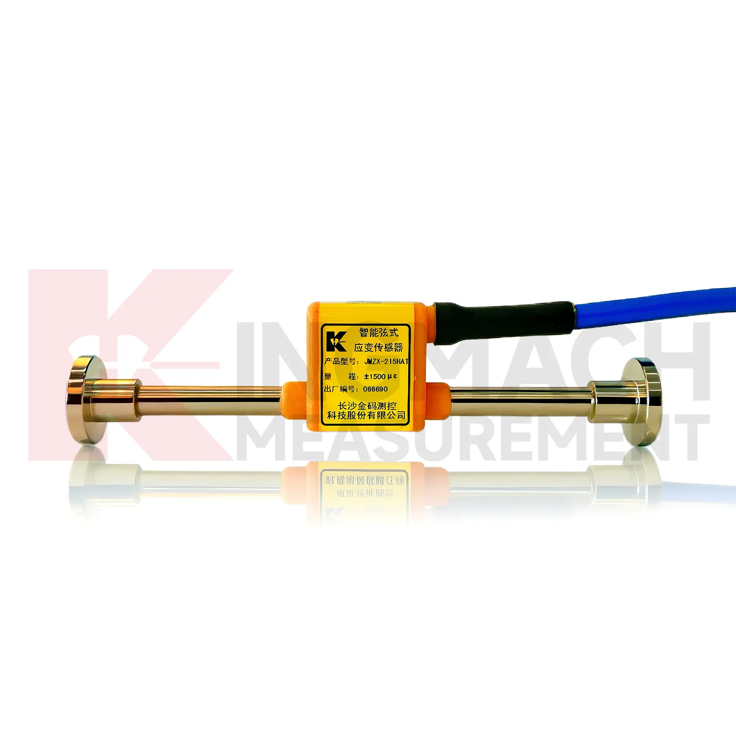
Smart vibrating wire strain gauge (embedment model) JMZX-215HA/215HAT/HB
View Details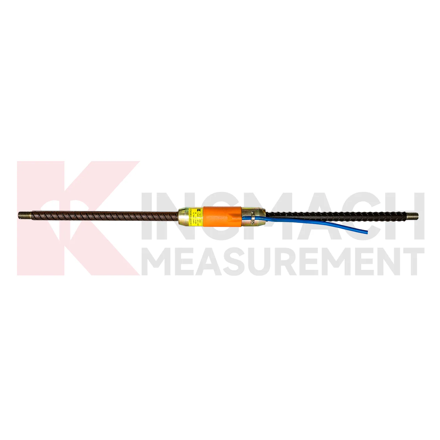
Rebar Strainmeters ( VW & Smart Type) JMZX-4XXHAT/HB
View DetailsFAQ
Almost all bonded foil strain gauges can be wired as a quarter bridge. You’ll need a three‑wire connection to the logger to compensate for lead resistance. Kingmach gauges come with solder pads clearly labeled, and the datasheet includes the color code for common logger terminal blocks. Just match the gauge resistance to the logger’s completion resistor—typically 120 Ω or 350 Ω.
This usually points to self‑heating or lead‑wire effects. A 120 Ω gauge draws more current at the same excitation voltage, which can warm the grid enough to change the resistance on low‑conductivity materials like plastics. Switching to a 350 Ω gauge cuts the current and power dissipation roughly in half. If the gauge is already bonded, check whether you’re using a two‑wire or three‑wire quarter‑bridge setup—an uncompensated two‑wire connection will add the cable resistance directly to the strain reading, mimicking drift.
In short, no. Bonded strain gauges are one‑time installations. The adhesive and carrier are designed to transfer strain, not to survive removal. Once you peel or solvent‑strip the gauge, the grid is damaged and the backing loses integrity. If you need temporary measurements, consider a clamp‑on extensometer or a removable strain‑gauge‑based clip transducer instead.
The self‑temperature compensation (STC) number printed on the gauge package corresponds to the thermal expansion coefficient of the test material. STC‑06 is typical for mild steel, STC‑09 for stainless steel, STC‑13 for aluminum, and STC‑00 for concrete-like materials. If you’re working with an exotic alloy, contact Kingmach with the expansion coefficient and we can suggest a matching gauge or provide a batch with a custom STC curve.
Accuracy depends more on your installation and calibration than on the gauge itself. A properly bonded gauge with a good adhesive and moisture protection can achieve repeatability better than 0.5% of full scale. The bridge nonlinearity error is usually negligible for strains under 3000 microstrain. The bigger error sources are misalignment, wiring, and the tolerance of the completion resistors in quarter‑bridge mode. Kingmach gauges themselves have a gauge factor tolerance of ±1%, which is typical and easy to calibrate out with a shunt resistor.
Share your product type, target capacity, and application requirements. Our team can review the details and recommend a practical next step.
If you are interested in our products or want to become our partner.
Please leave your contact information, our team will contact you as soon as possible.
Mail: [email protected]
Contact Us: +8613808434127
Address: No. 188 Tongzipo West Rd, Changsha, Hunan, China