
 EN
EN
 ar
ar bg
bg hr
hr cs
cs da
da nl
nl fi
fi fr
fr de
de el
el hi
hi it
it ko
ko no
no pl
pl pt
pt ro
ro ru
ru es
es sv
sv tl
tl iw
iw id
id lv
lv lt
lt sr
sr sk
sk sl
sl uk
uk vi
vi et
et hu
hu th
th tr
tr fa
fa ms
ms hy
hy ka
ka ur
ur bn
bn mn
mn ta
ta kk
kk uz
uz ku
ku
Real-Time Dam Safety Alerts with Differential Pressure Water Level Sensors
Key Takeaways An alert chain needs more than a sensor: define field in...

Load Cell Wiring Diagram: A Practical Guide
Wiring a load cell isn’t complicated once you understand the basic color codes and bridge configuration. Yet a simple mistake can lead to erratic readings or even damage the sensor. This guide walks through the typical wiring diagrams for strain gauge load cells, covering 4-wire and 6-wire setups commonly used in weighing and force measurement. We focus on practical steps and the most frequent pitfalls engineers face. At Kingmach, we often help customers troubleshoot wiring issues—many problems trace back to a few overlooked details. Whether you’re connecting to a digital indicator or PLC, starting with a clear wiring diagram saves time and avoids costly rework.
Technical Detail
Load cell wiring diagrams are essential reference tools for anyone integrating sensors into a measurement system. Most strain gauge load cells use a Wheatstone bridge circuit, requiring excitation voltage and delivering a millivolt signal. A standard 4-wire cable has Excitation+ (often red), Excitation- (black), Signal+ (green), and Signal- (white). A 6-wire cable adds Sense+ and Sense- leads (typically blue and yellow), which compensate for voltage drops over long cable runs. Kingmach supplies a variety of load cells for geotechnical and industrial monitoring, and our support team regularly fields questions about wiring. While each manufacturer may have slight variations, most follow the same conventions. The diagram you use must match your specific sensor and instrument. A key point to remember: never swap excitation and signal wires—this can burn the bridge. Always verify wire assignments with the data sheet before powering up. In field installations, shielding and grounding play a big role in noise rejection. Connect the cable shield only at the instrument end to avoid ground loops. For 4-wire to 6-wire hookups, jumper the sense lines at the connector, but be aware you lose remote sensing accuracy. Kingmach provides detailed wiring guides with its products, but the basics apply universally. Taking time to double-check connections against the wiring diagram prevents measurement drift, overload damage, and countless hours of troubleshooting.
News
Key Takeaways An alert chain needs more than a sensor: define field in...
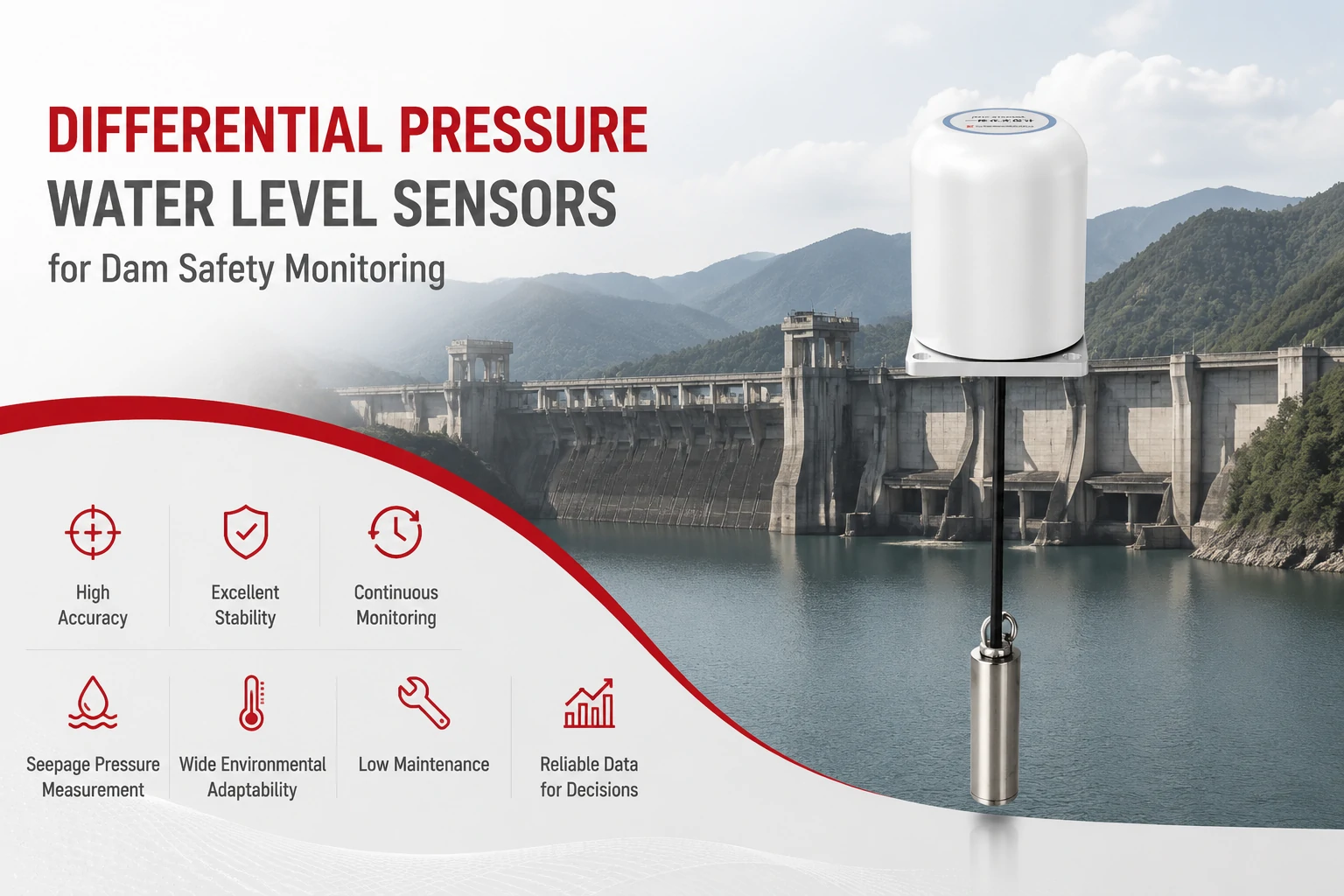
Key Takeaways The strongest fit is usually a confined, submerged, or s...
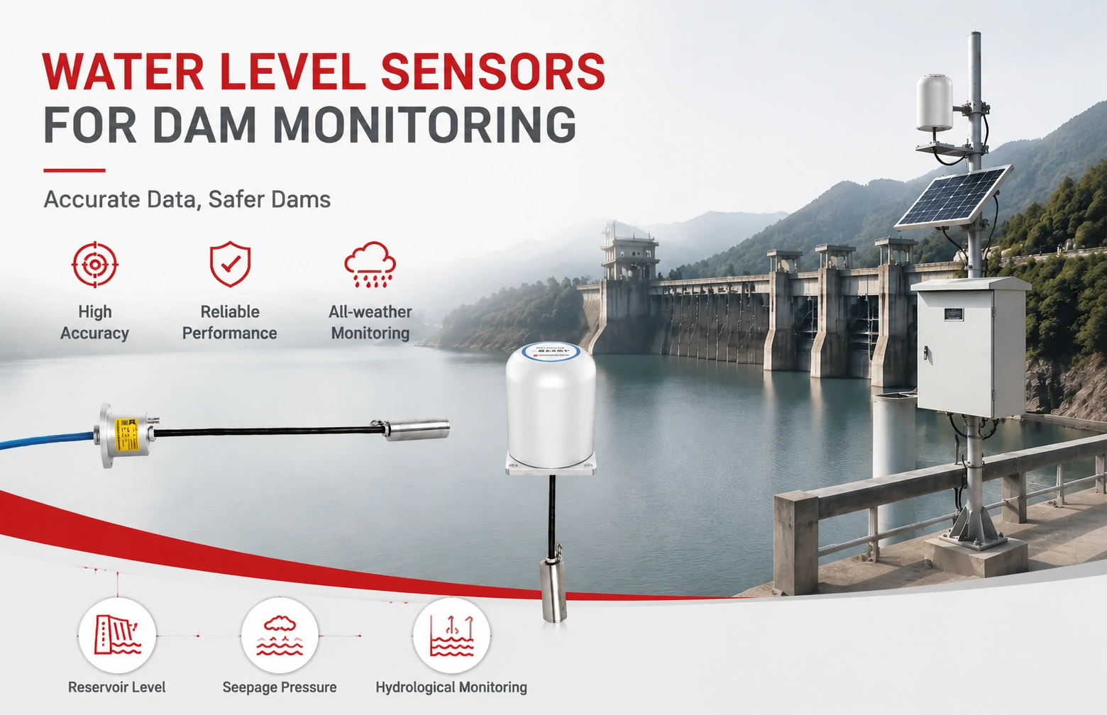
Kingmach Water Level Sensors for Dam Monitoring: A Buyer's Guide to Differential Pre...
Products
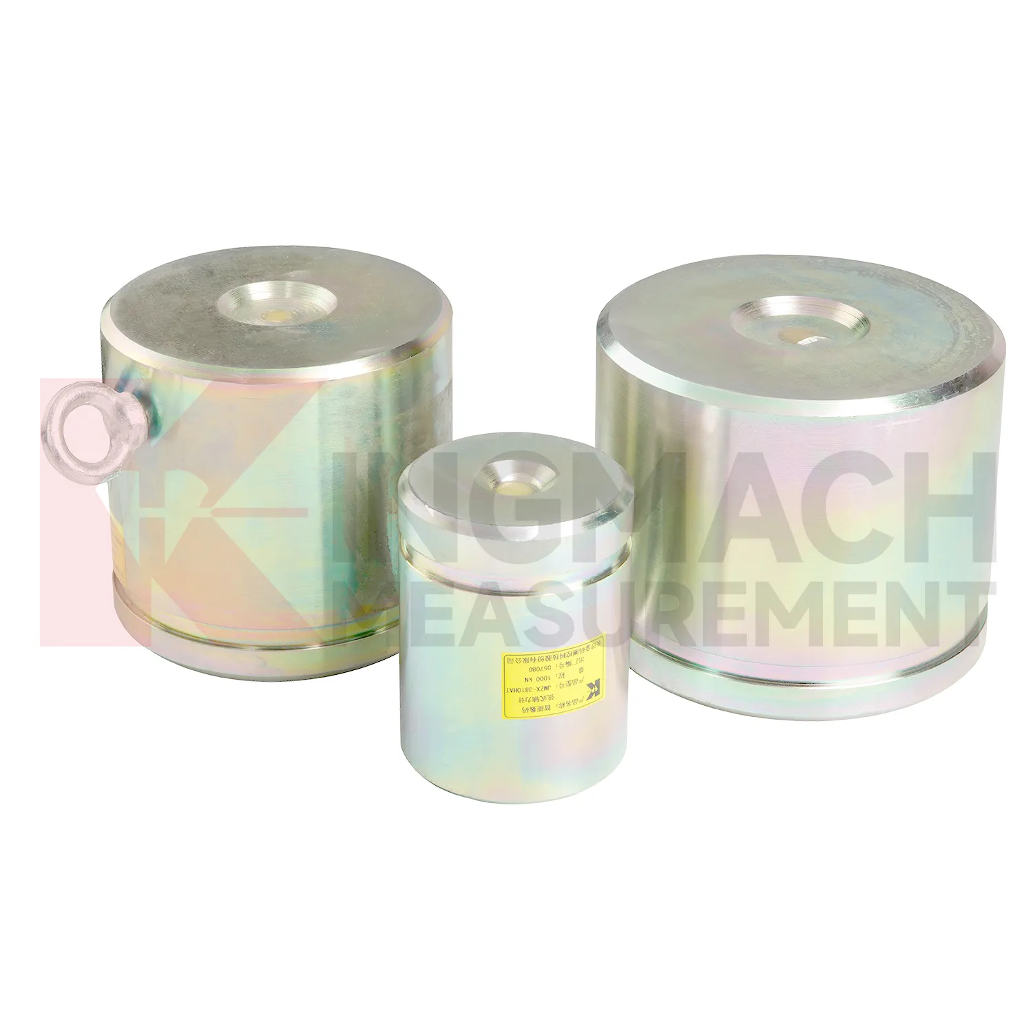
Axial Force Load Meter ( VW & Smart Type)JMZX-38XXHAT
View Details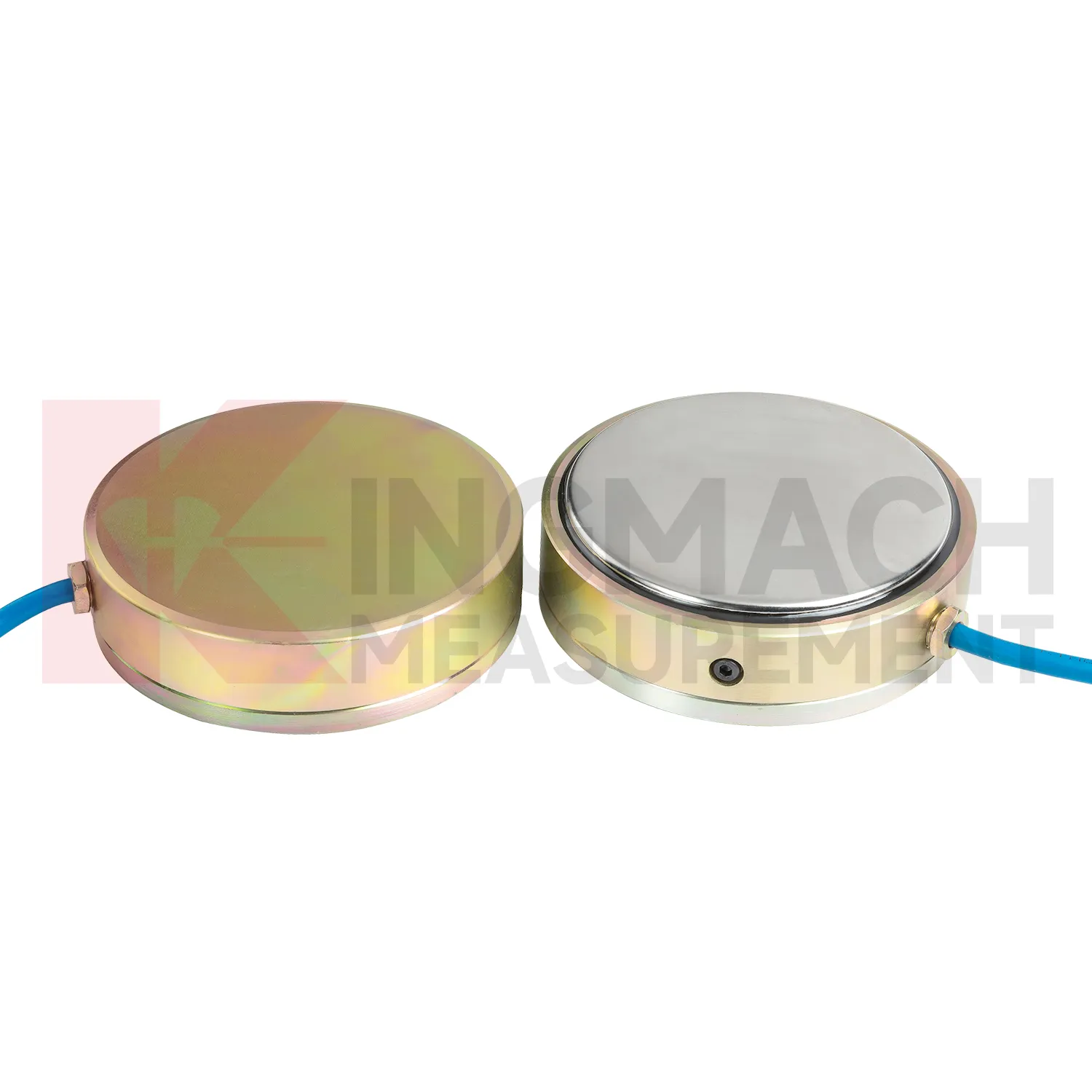
Earth Pressure Cell ( VW & Smart Type) JMZX-50XXAT/ ATM
View Details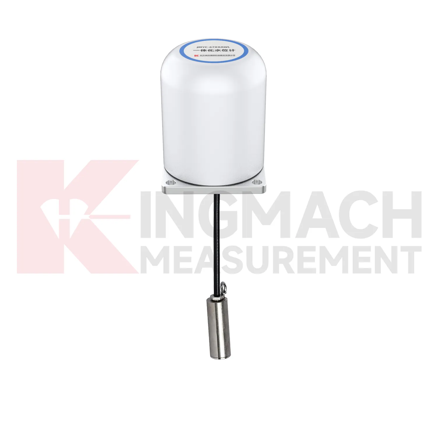
Integrated Wide-Range Differential Pressure Water Level Meter JMYC-67XXAWL
View DetailsFAQ
Most load cells use a standard coloring: red for Excitation+, black for Excitation-, green for Signal+, and white for Signal-. In 6-wire versions, blue and yellow often stand for Sense+ and Sense-. But never rely on color alone—always check the manufacturer’s data sheet because some brands deviate from this convention.
You can connect a 4-wire load cell by bridging the Sense+ to Excitation+ and Sense- to Excitation- at the indicator terminal. This locally senses the excitation voltage, but you lose the ability to compensate for cable resistance. For long cable runs, it’s better to use a load cell with sense wires to maintain accuracy.
Yes, unstable readings often point to poor connections or noise. Check that all wires are securely screwed down, the shield is connected only at the instrument end, and the cable isn’t running alongside power lines. Moisture in the cable or junction box can also cause drift, so look for corrosion or damaged insulation.
You can extend it, but adding length increases resistance and makes the signal more susceptible to electrical noise. If you must extend, use a 6-wire system for sense compensation, use shielded twisted-pair cable, and solder or use proper crimp connections—never just twist wires together. Recalibrate the system after any extension.
Start by measuring resistance between the excitation leads—it should match the datasheet (typically 350 or 1000 ohms). The signal leads should show similar resistance. Check for shorts between shield and any wire. With no load, the signal voltage (mV) should be near zero. If values are way off, you might have swapped excitation and signal wires.
Share your product type, target capacity, and application requirements. Our team can review the details and recommend a practical next step.
If you are interested in our products or want to become our partner.
Please leave your contact information, our team will contact you as soon as possible.
Mail: [email protected]
Contact Us: +8613808434127
Address: No. 188 Tongzipo West Rd, Changsha, Hunan, China