
 EN
EN
 ar
ar bg
bg hr
hr cs
cs da
da nl
nl fi
fi fr
fr de
de el
el hi
hi it
it ko
ko no
no pl
pl pt
pt ro
ro ru
ru es
es sv
sv tl
tl iw
iw id
id lv
lv lt
lt sr
sr sk
sk sl
sl uk
uk vi
vi et
et hu
hu th
th tr
tr fa
fa ms
ms hy
hy ka
ka ur
ur bn
bn mn
mn ta
ta kk
kk uz
uz ku
ku
Differential Water Level Gauge
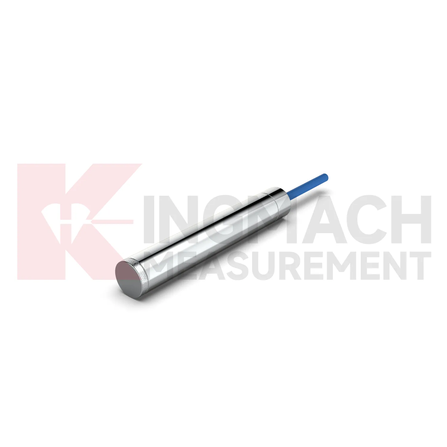
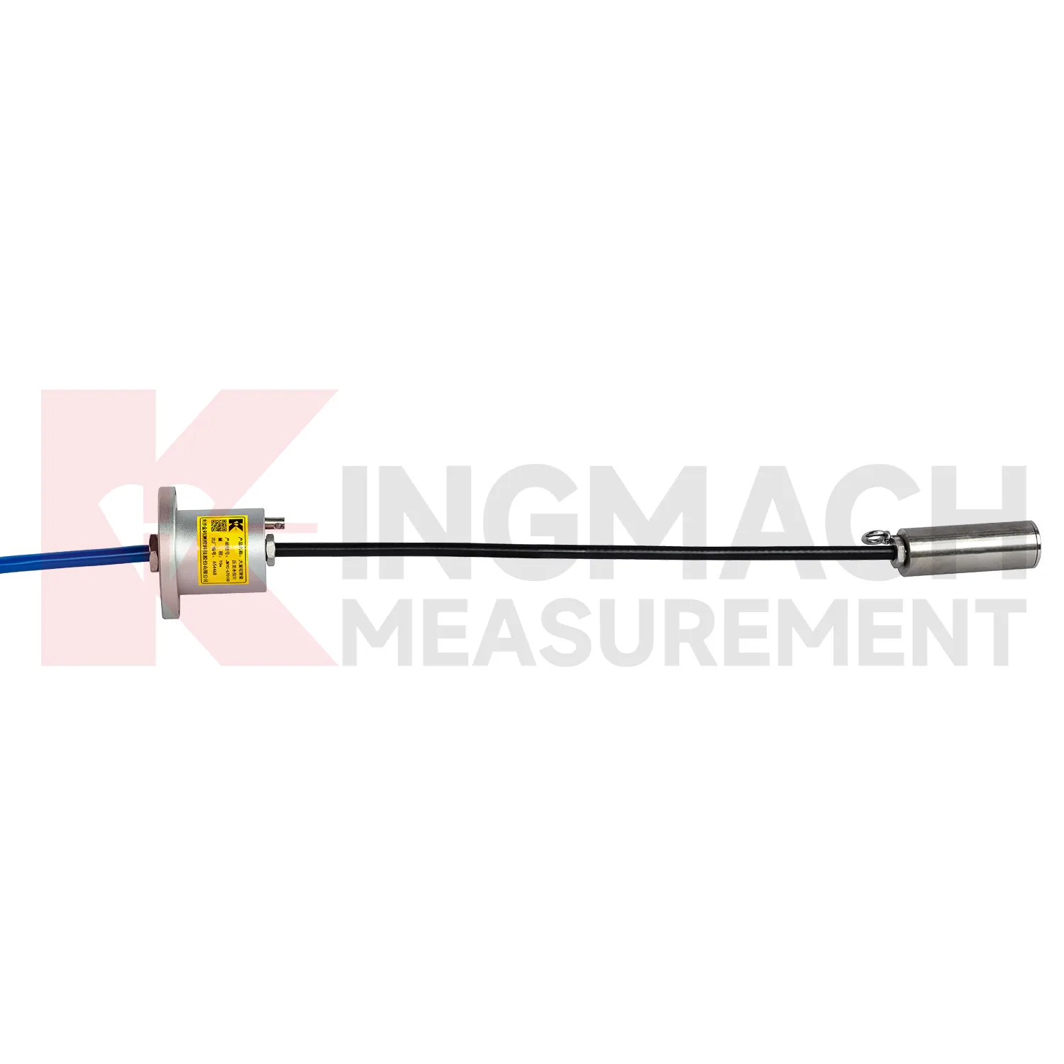
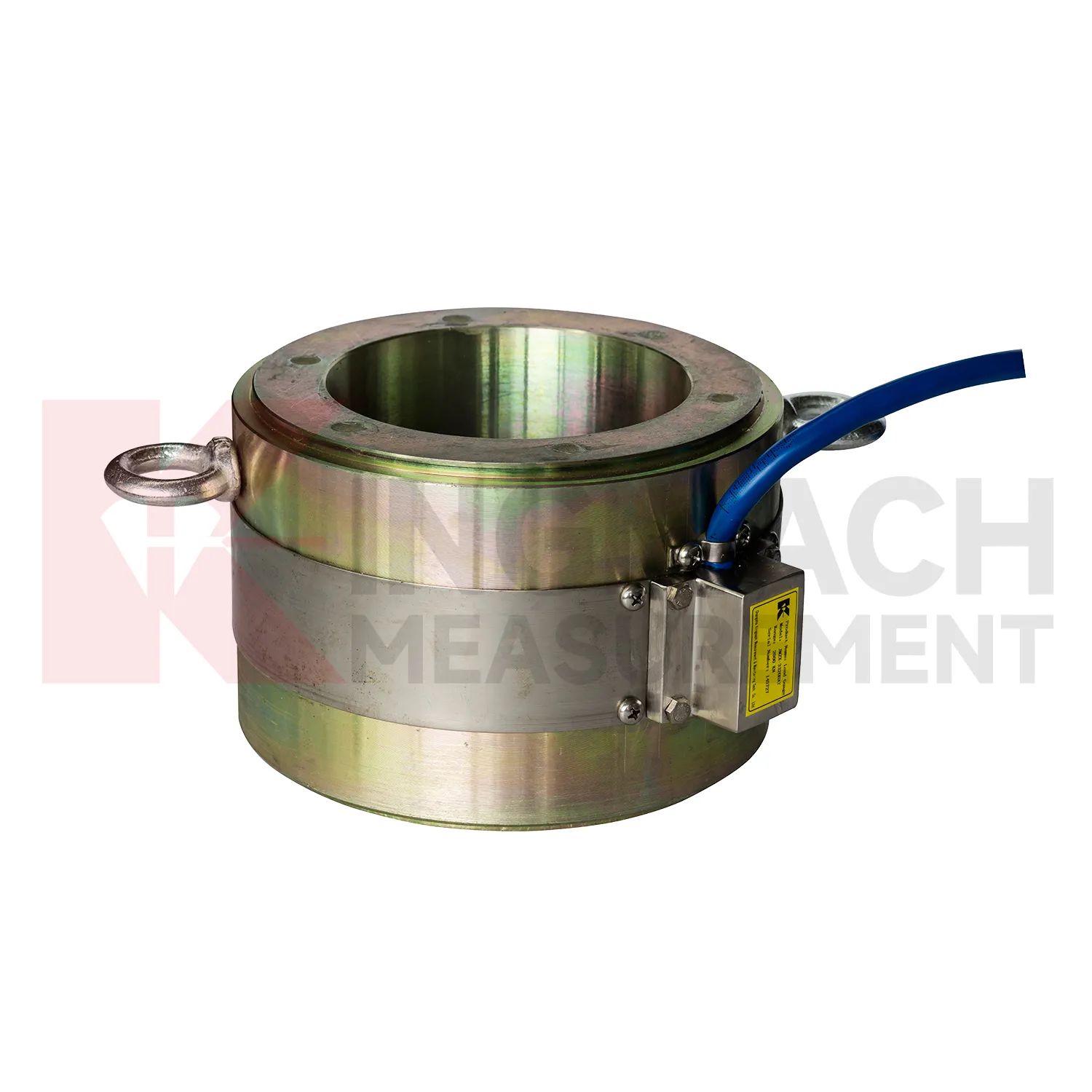
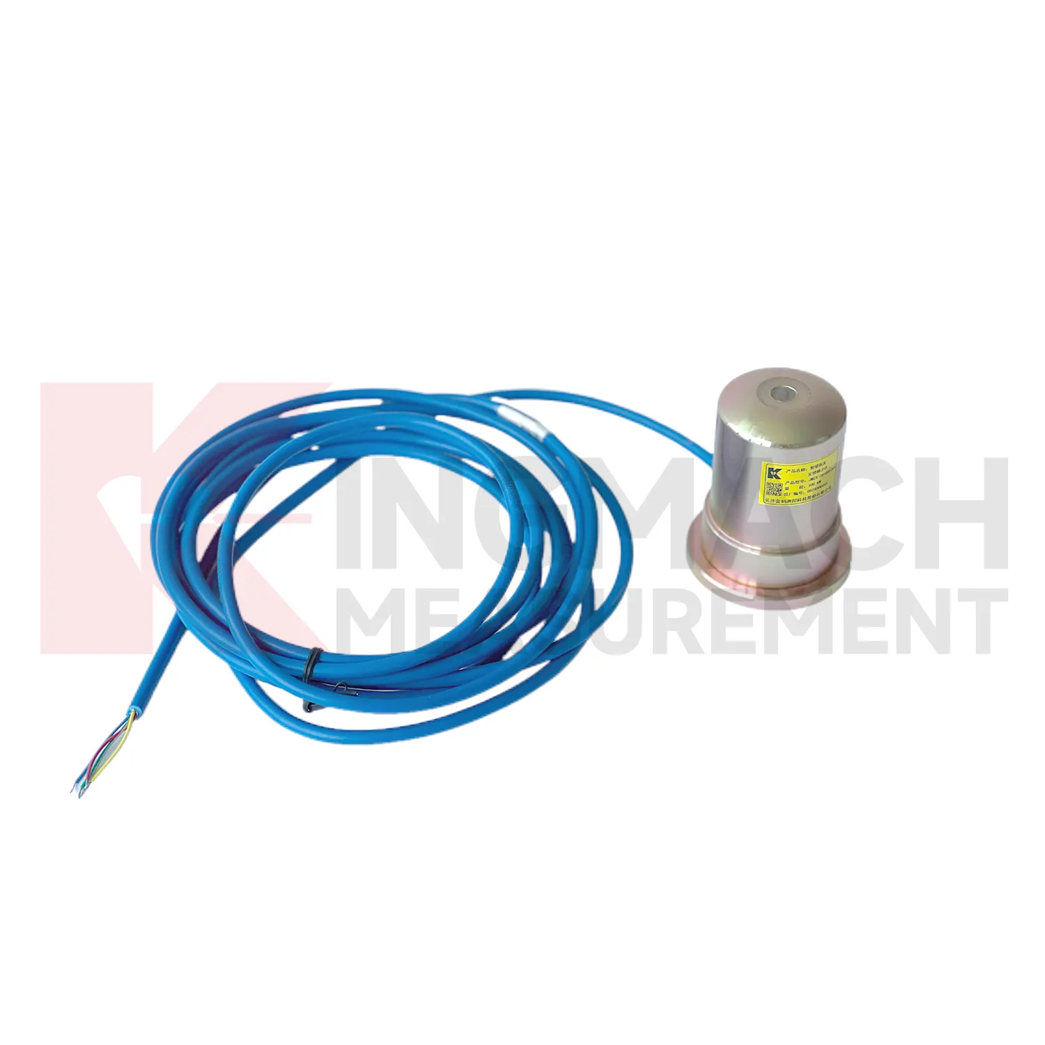
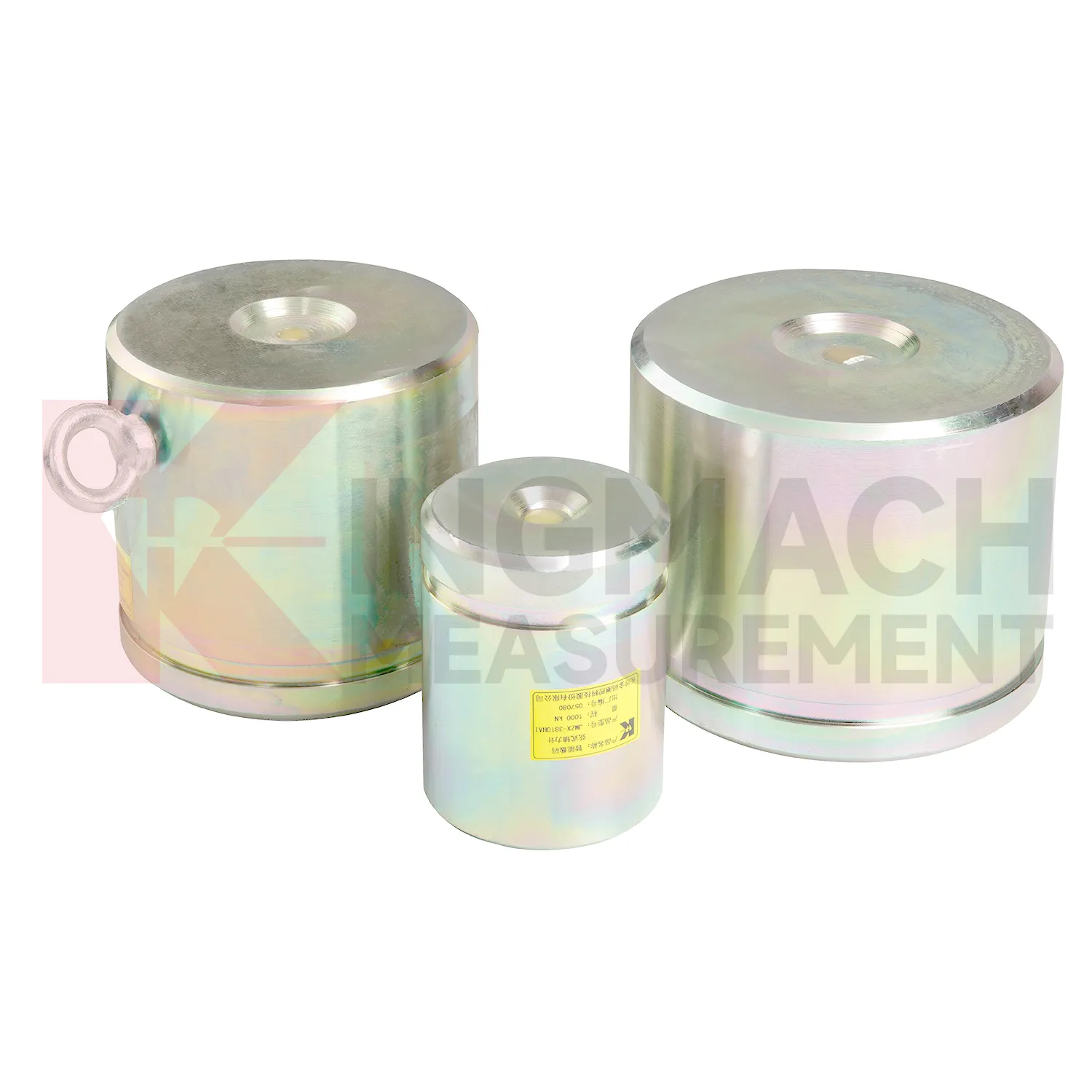
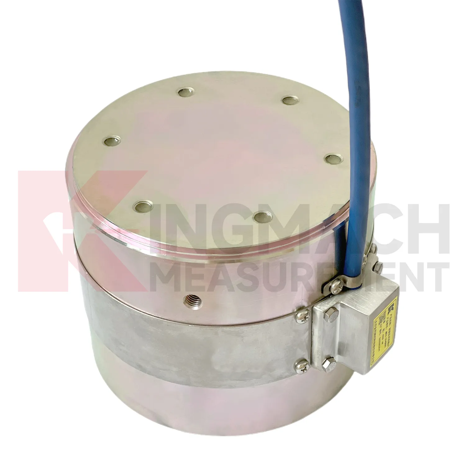
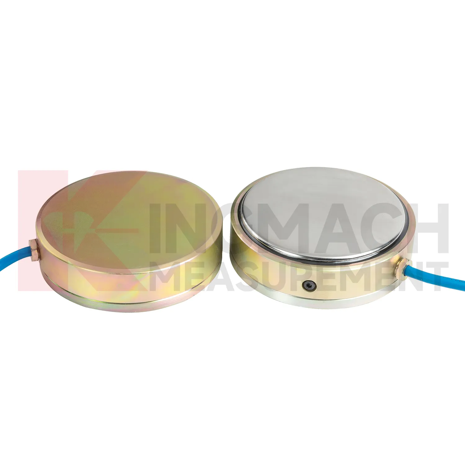
Kingmach Differential Water Level Gauge product information is especially helpful during early engineering review because it gives model families rather than one generic device. The JMZX-3XXXHAT hollow load cell is tied to annular multi-string construction, elastic steel, ultra-high-strength vibrating wires, anchor welding, temperature correction, and 500 kN to 8000 kN ranges. The JMZX-35XXHAT solid load cell is tied to compression monitoring, 1000 kN to 10000 kN ranges, 0.1 kN resolution, and 0.5%FS precision. The JMZX-38XXHAT axial force meter is tied to steel support measurement, 200 kN to 3000 kN ranges, and 1 MPa waterproof performance. Those distinctions guide model selection before purchase. For a bridge, the force path may require hollow or solid construction. For a tunnel support, direct axial force display may be more practical. For soil pressure, MPa range and buried durability matter more than kN capacity. Matching the type to the load path prevents expensive changes after delivery. The product pages also show that standard models and customized versions may exist side by side. That is important because site geometry, force range, and available clearance may require confirmation before the load point can be ordered with confidence. It also gives the contractor clearer limits for installation geometry, cable routing, waterproof protection, and calibration review before the work reaches the field.
Application of Differential Water Level Gauge
In bridge monitoring, Differential Water Level Gauge can be used at cable anchor heads, stay cable force points, pier supports, bearing test positions, and pile load test setups. The pain point is simple: a bridge can redistribute force before visible cracks or displacement appear. Hollow load cells such as the JMZX-3XXXHAT cover 500 kN to 8000 kN and are built around an annular multi-string structure with temperature correction and waterproof durability. Solid load cells reach 10000 kN with 0.5%FS precision, which suits high capacity compression points and bearing capacity checks. During construction, readings can confirm prestressing, lock-off behavior, and support load transfer. During operation, the same point can be reviewed after heavy traffic, temperature swings, maintenance work, or extreme weather. Force data becomes more meaningful when compared with displacement transducers, settlement points, tiltmeters, and visual inspection results. For long span bridges, a load trend that drifts slowly can be more important than a single high reading, because it may reveal relaxation, seating loss, or uneven force sharing. Cable exit direction, waterproof joint location, inspection access, and whether the point will be buried or exposed should be decided before installation. Those details are easy to ignore in drawings, but they often decide whether a field crew can verify the reading later without disturbing the structure.
The future of Differential Water Level Gauge
In tunnels and foundation pits, future Differential Water Level Gauge use will move toward faster construction stage feedback. Axial force meters with 200 kN to 3000 kN ranges, 0.5%FS accuracy, direct kN display, and 1 MPa waterproofing already suit support load monitoring. The next step is pairing those readings with excavation depth, support installation time, groundwater level, wall displacement, and site progress records. LoRa or 4G gateways can reduce manual rounds where access is unsafe or work is moving too fast. Edge devices can flag missing channels, abnormal drift, or readings that changed after a cable was disturbed. This is different from a vague smart site label. It is a specific workflow where the sensor reading is checked against the work stage that should have caused it. As urban underground projects face stricter monitoring requirements, instruments that combine rugged installation, direct force output, and platform access will fit the way contractors actually manage risk.
Care & Maintenance of Differential Water Level Gauge
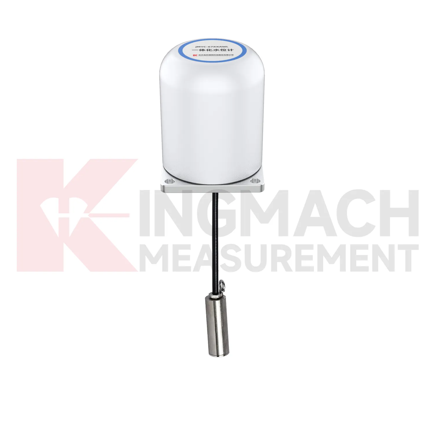
For Differential Water Level Gauge, procurement and maintenance teams should agree on records before the product reaches the site. The box should not arrive as an anonymous device. The file should contain model, range, dimensions, calibration coefficient, certificate requirements, cable length, readout method, and any custom order notes. Axial force meters are often customized, with model, range, and dimension confirmed at order and lead time often planned around 20 to 30 days. During installation, check that the delivered item matches the support diameter, bearing plate layout, and data acquisition plan. During use, keep warranty, calibration, inspection, and repair notes together with the monitoring record. Protect the sensor from overload, impact, water entry, and unauthorized rewiring. If the project changes from manual reading to automated collection, verify scaling and units before comparing new data with older values. Maintenance is easier when the administrative record is as tidy as the hardware installation. Confirm changes before handover.
Kingmach Differential Water Level Gauge
Differential Water Level Gauge often sits between design intent and field behavior. Drawings may state the expected force, but site loading can change when excavation sequence, concrete curing, traffic, reservoir level, grouting, or prestressing work changes. Kingmach supplies sensors and acquisition equipment for bridges, tunnels, dams, subways, slopes, foundations, railways, buildings, and hydropower projects. In these settings, the sensor helps reveal whether a member is carrying its share of the load or taking more than expected. The instrument must fit the force range, the bearing surface, the environmental exposure, and the data workflow. A high capacity sensor with poor installation records is still hard to trust. A moderate range sensor with clear calibration, stable zero, protected cable, and a clean reading plan can produce stronger evidence. For that reason, force monitoring should be planned alongside installation details, not added after the site has already become crowded. This is especially useful when the monitored point becomes hidden after the next work stage.
FAQ
Q: How can Differential Water Level Gauge be connected to a monitoring platform? A: Use compatible readouts, acquisition modules, data loggers, DTUs, and software platforms according to site access, cable distance, power, and reporting requirements. Q: What makes smart models useful in large networks? A: Stored model data, calibration coefficients, zero values, temperature data, and measurement records reduce confusion across many channels. Q: Should manual readings still be kept? A: Yes, manual checks are useful after installation, maintenance, abnormal alarms, or logger changes. Q: How should alarm limits be set? A: Base them on design stage, sensor range, expected load change, temperature behavior, and nearby monitoring points. Q: What data should be reviewed together with force? A: Settlement, displacement, tilt, water level, pore pressure, rainfall, temperature, construction events, and inspection notes.
Reviews
Andrew Lee
The visualization software is intuitive and powerful. It helps us analyze monitoring data efficiently.
Michael Anderson
The strain gauges and load cells are extremely accurate and stable. They performed very well in our bridge monitoring project. Highly recommended!
Latest Inquiries
To protect the privacy of our buyers, only public service email domains like Gmail, Yahoo, and MSN will be displayed. Additionally, only a limited portion of the inquiry content will be shown.
Ava***@gmail.comAustralia
Hi, I am looking for reliable tiltmeters and accelerometers for structural health monitoring. Please...
Sophia***@gmail.comUnited Kingdom
Good day, we need environmental monitoring sensors including temperature, humidity, and wind sensors...
Related product categories
- calibration of load cell theory
- load cell failure
- load cell technology
- strain gauge load cell wiring
- diagram 4 wire load cell wire connection
- load cell accuracy calculation
- load cell amplifier circuit
- load cell calibration procedure
- load cell excitation voltage
- load cell unit of measurement
- mounting load cells
- strain gauge with load cell